Showing posts with label electronics. Show all posts

Monday, February 25, 2013

Back to basics: Urms

Following a question on PhysicsForum concerning the total Urms (Root Mean Square Potential Difference) due to the remaining alternating component in the half wave rectifier.

The half wave rectifier is obtained by using a single diode to let only half of the sine wave go through.


The source can be any signal, but the most frequent would be a sine signal, for instance coming out of a transformer.If we neglect the drop due to the diode, the potential difference on the load will be half of the sine wave.

Now comes a big question: what DC potential difference would be needed to get the same energy dissipated through a purely resistive load? If we call u(t) the varying, periodic signal and U the potential difference needed to generate the same energy, we get


Where T is the signal's period. Remembering that I=U/R (Ohm's law), we get that

R is constant in time, it can be taken out of the integral, and we end with


Let's go through a few examples.

Sine wave of frequency f and peak Up.

Such a signal can be described by the function


Where ω is the pulsation and is


Rectangular wave of amplitude Up and duty cycle ω


The duty cycle ω is the fraction of the period during which the signal will be at Up. Otherwise, the signal is 0.


And thus

And finally ...

Half wave rectified sine of amplitude Up and frequency f.

This is almost the same as for the full sine wave, except that instead of taking the integral from 0 to T, the integral goes only to T/2. This gives the result

Before moving to a different topic, let's establish a property we will use later.

Let's consider the signal u(t) with period T defined by


And


We will prove that


Let's go!


The part labeled A develops like this

The part labeled B is easy to develop and gives

Substituting back, we conclude that


This result will help us later.

{To be continued!}

Saturday, November 3, 2012

Discrete FPGA will probably win the 7400 logic competition

This is a mega hack!

Discrete FPGA will probably win the 7400 logic competition:

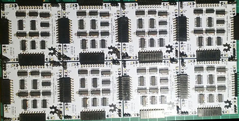
For this year’s 7400 logic competition, [Nick] decided to build an FPGA out of logic chips.
Perhaps a short explanation is in order to fully appreciate [Nick]‘s work. The basic component of an FPGA is a slice, or cell, that performs boolean operations on its input and sends the result on its output. The core of these slices is a lookup table – basically a truth table that stores the result of every possible input combination.
One very easy way to implement a lookup table is to use a RAM or EEPROM chip. By tying the address lines of an EEPROM to the input and the data lines to the output, it’s possible to create a single slice of an FPGA very easily.
Unfortunately for [Nick], 74-series memories have long been out of production. There is another option open, though: shift registers. A shift register is basically an 8-bit memory chip with parallel inputs, so combining a shift register with an 8-input multiplexer is a very simple way to implement a 3-input, 1-output FPGA slice.
After figuring out how to tie these slices to bus lines, [Nick] needed a way to program them. Verilog or VHDL would border on insanity, so he wrote his own hardware description language. It’s certainly not as powerful or capable as the mainstream solutions to programming an FPGA, but it’s more than enough.
In the video after the break, you can see [Nick]‘s overview of his very large 8-slice FPGA while he runs a combination lock and PWM program. All the code, schematics, and board layout are up on [Nick]‘s git if you’d like to build your own.


Filed under: hardware

Sunday, July 8, 2012

Falstad Circuit Simulator - Transistor Graph

Recently, and after almost 15 years without touching a component, I decided to go back to my roots - electrical engineering - and annoy again transistors and other diodes. To quickly test, I use a java applet on the Falstad website.

The components are idealized, and for instance, there is only one NPN transistor - forget about the BC547 A through C, the 2N2222 and other BD135 - whose only changeable parameter is its DC gain β, 100 by default.


A need I had was to have the graph UCE/Ic for various Ib.  I decided to plot it myself.